Meet the Artemis Dual Deploy Rocket! Part 2
Welcome to part two!
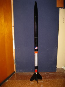
At this point, the paint scheme is done, and you are now able to see the rocket take shape. Artemis X2-05.

- Artemis X2-05 “Pathfinder with its paint scheme. The red square below is a compartment that holds the drogue chute ejection charge.
The next step in the development cycle is the set up to test all the ejection systems.
The ejection charge canisters are made from small sections of styrene tubing with a Quest G2 igniter epoxied to one end. The ejection charges are behind an ejection baffle system specifically designed to work while being extremely close to the charge canister.
This requirement of mine introduced more variables to contend with, which made for interesting times!
Drogue parachute deployment system
The first of the interesting steps involves getting the drogue chute charge canister behind an ejection baffle which is shared with the charge on the engine.
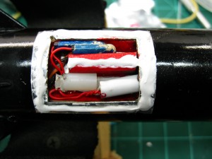
The engine’s ejection charge is used as a backup in the event something goes wrong with the electronics. My solution to the shared baffle dilemma was to place a compartment on the lower half of the rocket which gives access to the shared baffle system. The access door uses rubber silicone to seal the compartment so that the pressure is directed towards the area of interest, and not just leak out of the door.
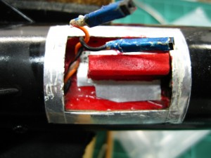
Inside the compartment is an area for the connections to “live”, and another for the charge to sit in. There is a small hole which allows the charge to slip into.
In the picture of the loaded compartment, you can see the ejection charge canister to the lower right side of the compartment.
Behind it is a scrap plastic piece to prevent the recoil forces from pushing the canister back out of the opening. On the upper side of the compartment you’ll see the electrical connections.
Main parachute deployment section
The upper baffle for the main parachute deployment system was challenging in some ways, but easier to implement than the drogue. For one, there is no need to share the baffle system with the motor.
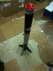
The canister for the main parachute lives just above the electronics bay. There is another part that serves as the mount for that ejection charge. The main charge fires sideways, so to prevent that force from blowing a hole int he side of the rocket over time, there is a thin aluminum shield piece to protect the body tube.
The moment of truth.
Two days before the maiden flight, I put Pathfinder through its paces in a series of ground tests designed to see if everything works as planned, and to hopefully expose any weaknesses in the design I may have overlooked. The ground tests went well – proving the designs worked well. One weakness that was exposed was the friction fit between the top of the electronics bay and the upper baffle. A minor change to the design to allow for taping the two sections together with a bit of aluminum tape solved the issue.
httpv://www.youtube.com/watch?v=R9X1MkpH8HM
So, now, as the countdown ticks away to the October 8th maiden voyage, I’m off to address a ton of loose ends!
((( )))


