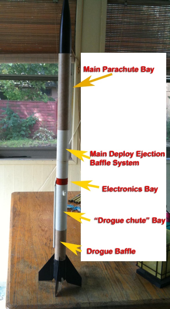
Project Artemis – An overview.
Project Artemis: March 2010 – April 2013
The Artemis rocket was born from project Aquila, which really had no purpose originally. It was my first original rocket design in years. I was getting my feet wet after being out of the hobby for about 30 years.
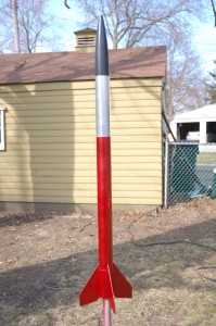
The “XR-1” rocket “Aquila”
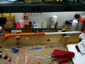
The Aquila rocket on the workbench.
After the excitement of seeing something I designed fly successfully, ideas came to mind that I wanted to experiment with and develop. The Aquila rocket was a tiny rocket, and that limited any chances to experiment. So a new rocket design was needed. Thus, project Artemis was born with a list of objectives to accomplish.
The objectives of the XR2 / Artemis program were:
- Collect experience data for designing an ejection baffle system for use in all future rocket designs.
- Collect experience data for developing modular rocket designs.
- Experiment with carrying payloads of various weights and collect experience data there.
- Develop on-board power techniques to allow the ability to carry active electronics to apogee.
- Test radio telemetry techniques.
- Collect extensive data on launch vehicle performance across a wide range of weather conditions.
- Experiment with using low thrust long bun motors.
- Experiment with stronger higher thrust motors for early data for progressing to mid power rocketry, with the goal to developing my first high power rocket.
- Launch payloads to a maximum of 2000 feet in altitude.
Fifty-five Artemis rocket launches were performed between March 2010 and April 27, 2013. Fifty-three of which flew specific missions to test the technologies I was developing.
To carry out the bulk of these experiments, three Artemis launch vehicles were initially built to carry out these missions on an intense schedule. Since it would take some time to outfit the rocket for some of these tests, the multiple rockets allowed for a six-week window to prep each one for its mission. This allowed them to be in a service rotation to prevent long gaps in progress.
Each rocket was given the designation “XR” for “Experimental Rocket” and a number designating the “drawing board design number” for the rocket.
The model designation for the Artemis rocket was “XR2” for “Experimental Rocket design #2”. (Aquila was post-designated as XR1.)
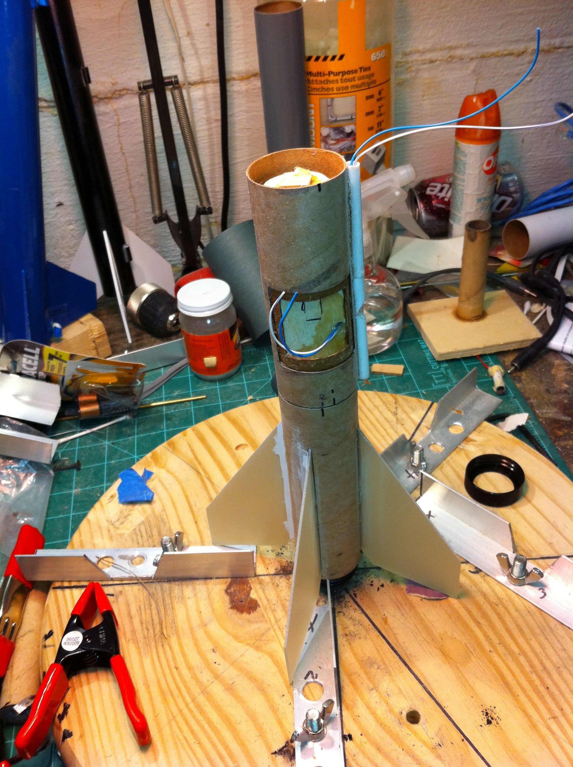
To save time building a fleet of rockets, I decided to build around the fin can of the Estes “Blue Ninja”’ rocket kit. This saved time on building fins as this kit had pre-made plastic fins. All other components were custom designed around this fin can assembly. Fabricating my own fins was a project reserved for the next rocket design under consideration.
The first three Artemis vehicles built were:
XR2-01 – “Big Red”
XR2-02 – “Bumble Bee”
XR-03 – “Garfield”
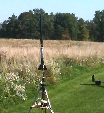
XR-2 / Big Red in the “1B” configuration
XR2-01 “Big Red” was designed and built during the beginning months of 2010. During the early parts of Spring, the model underwent ground tests to check the viability of the baffle design, and inspect for problems. Some design changes were made based on observations. Eventually, she was ready for her maiden voyage.
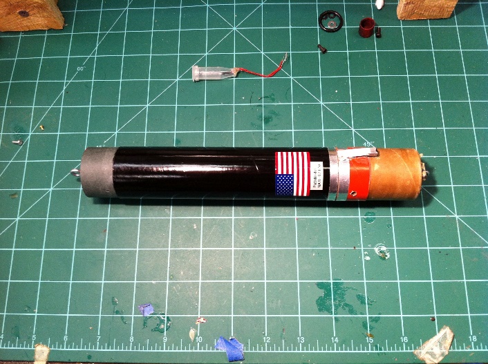
The Artemis rockets were flown using one of three configurations. The “1A” configuration, which featured a narrow-elongated payload section.
The “1B” configuration – which was only used to test the booster. This configuration essentially means, “slap the black nose cone on top of it”.
The “1E” configuration, which would become the “iconic” configuration for many of the early test flights.
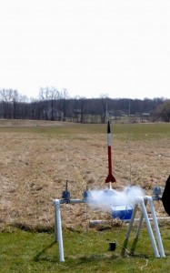
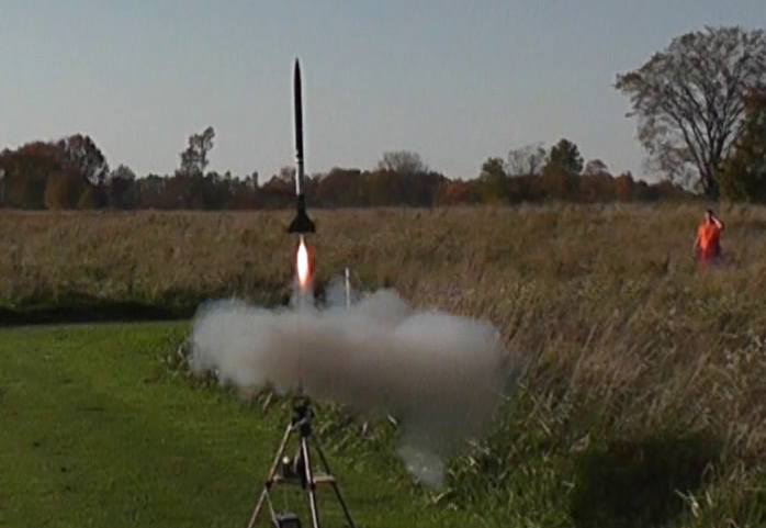
Big Red on its maiden launch
A fourth configuration eventually emerged, and was used in the latter half of the program with the dual deployment version of the rocket. This configuration was simply referred to as “XR2/DD MKI” and “XR2/DD MKII”. More on that later…
Big Red being prepped for ground tests in the “1B” configuration.
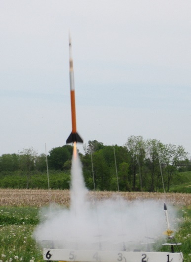
March 27, 2010
Big Red lifted off successfully for the first time, and flew three other test flights on that same day. These tests proved the design was stable, and sound. These missions were designated as “ALS-001 through ALS-004”. ALS was short for “Artemis Launch System” and the numerical designation was the mission number.
Each of Big Red’s first four flights were flown on Estes D12 motors, carrying the rocket to an estimated altitude of around 600 feet. Work was progressing on the other two sister rockets in preparation for extensive tests. Based on observations from Big Red’s test flights, last minute design changes were made to the next two rockets to make them lighter, yet just as strong, which would allow for heavier experimental payloads to be used in future missions. This also would allow them to use a motor I was thoroughly fascinated by, which was the Estes E9. This motor places strict design challenges upon a rocketeer, as they are low thrust / log burn motors. A properly designed rocket would be able to fly relatively slowly to high altitudes with this motor! While Big Red’s flights were a success, one troubling event did happen. Upon post flight inspection, I found that the internal stuffer tube had partially collapsed. I did not know why this happened at the time, but as a pre-caution, one of the last minute design changes to the next two Artemis rockets was to reinforce the stuffer tube so that this would not happen to them. Big Red underwent careful repairs to repair the damage and investigate what happened. The answer would not become apparent for some time later on a different rocket.
Artemis X2-01 “Big Red” lifting off on its maiden voyage.
May 15, 2010
This was the big day for the maiden voyages of Artemis rockets “Garfield” and “Bumble Bee”.
These launches occurred during GLRMR X (Great Lakes Regional Meet Revisited 10). It was my first exposure to really big high power rockets! Anyway….
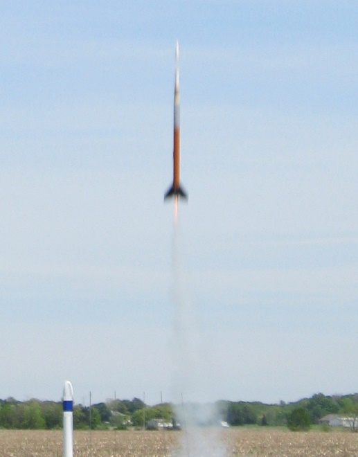
ALS-005 liftoff
Garfield flew its first two missions (ALS-005 and 006) in the “1B” configurations, and it marked the last time that configuration would ever be used. It’s third mission, ALS-007, was flown using the “iconic” “1E” configuration. All three flights were on the Estes D12 motor.
Next up that same day was Bumble Bee’s maiden launch. Bumble Bee flew using the “1A” configuration for all three of her maiden flights (ALS-008 through 010). Mission ALS-008 used the Estes D-12 motor. The next two were using the coveted E9 motor, and the flights were quite a site to see. Bumble Bee flew flawlessly and majestically on that motor. Just about every one of the early Artemis flights used the E9 motor from that point forward.
The day concluded with Garfield lunching two more times (ALS-011 and 012) – this time on the E9 motor as well. Flight ALS-011 used a small electronic altimeter to give the official altitude of the rocket – which was 845 feet.
All the E9 launches reached an estimated altitude of 800 to 950 feet, which was then the highest altitude for ANY rocket I’ve ever owned.
ALS-011 liftoff
The test flights of Garfield and Bumble Bee proved the lighter designs, and the reinforced stuffer tube design seemed to hold up just fine. May 15 2010 was a breezy day, and the Artemis rockets handled this breeze just fine on the E9 rocket. This was a concern as the general rule for rocket stability is that a rocket should be traveling a minimum of 35 miles per hour when leaving the guide rod to ensure a stable straight flight. Using the E9 motor, the rockets were traveling about 24 MPH from a three-foot guide rod!
May 23, 2010
Week number two of GLRMR X. The weekend activities included the return of “Big Red” to flight – this time in the Artemis “1-E” configuration.
But first up on the pad was Garfield on launch ALS-013 – this time using the Artemis “1-A” configuration. On an E9 motor. Estimated altitude was around 800 feet. Big Red launched (flight ALS-014) using an E9 motor as well, and the fight was textbook.
Garfield launched again in the “1-A” configuration on flight ALS-015. During the deployment phase at apogee, the elastic shock cord broke. Was the first in a small series of failures here that led to the use of Kevlar for recovery harnesses. More on that later as well…
The day concluded with Garfield launching using a nice new (painted) “1-E” section, though this time on my first launch with the Artemis design using a composite motor, which was an F-12 J motor. This placed Garfield at an estimated altitude of around 1200 feet…another altitude first for me.
These flights were primarily testing the consistency of the baffle system and allowed me to get a feel for improving my skills at putting the rockets on a trajectory to recover them as close to the launch pad as possible.
June 12, 2010
Philadelphia lifts off into the sky
This day was a breezy one. Since the Artemis boosters were not flown on winds this high (about 10 MPH), I decided to do a low altitude test launch of Bumble Bee in the Artemis 1E configuration first. Bumble Bee lifted off on mission ALS-17A using a D-12 motor. The flight was fine, and the winds were not much of an issue as far as safe flights were concerned. ALS-17B was next, and Bumble Bee lifted off on an E9 motor next. Once again, performance was nominal.
A big moment as the latest Artemis rocket, XR2-04 / “Philadelphia”, was put to the test on its maiden voyage. Of note was a new baffle design being tested to prevent an annoying issue with the ones currently in use. When composite motors are used, the plastic cap that holds the ejection charge in would become wedged into the baffle systems of Garfield and Bumble Bee. Philadelphia was also notably lighter than the other Artemis rockets.
Philadelphia took off on mission ALS-18A (Artemis “1-E” config.), its maiden test launch. Both this flight, and ALS-18B were a success, and no issues were noted.
Because of its lighter design, the altitude achieved with Philadelphia was notably higher than that of the other rockets on the same motor.
Another take-away from these flights was the establishment of the 12 MPH rule. The Artemis Launch Vehicle (because of its fin area) was restricted to flying when ground winds are less than 12 MPH.
June 18, 2010
This series of launches were held at one of the Streetsboro city parks. My club was invited to demo and fly rockets as part of their movie in the park event. Of note here is that these flights were the first to be flown at dusk.
Philadelphia was up first for flights ALS-019 and ALS20. Both flights were picture perfect. Bumble Bee closed out the evening by launching on mission ALS-021 just as the sun was setting, and the view was spectacular!
July 10, 2010
July 10th was the date for dual purpose test flights. The first was to be the next Artemis launch on a full mid-power composite motor. Also part of this full power test was to load the payload compartment with a full weight load (ballast) to approximate the weight of the proposed electronic systems for dual deploy flight missions.
Garfield was used for these tests in the “1-E” configuration, and was launched on missions ALS-025 and ALS-027 using the Aerotech E15 motor. Estimated altitude with this load was around 1000 feet.
ALS-025 was a launch with the ballast simulating the weight of electronics. ALS-027 was flown on the same motor, but without a payload.
Bumble Bee flew missions ALS-026 and ALS-028 on an E-9 motor in the “1-A” configuration.
July 25, 2010
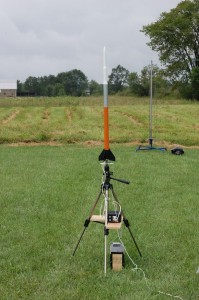
Pre-launch pic of “Garfield” on the new tripod-based launch pad
The Artemis rockets were tasked with testing my new launch pad. I’ve been using the club’s launch pad, and it was time to come up with my own ground support system. Components of this system were being developed for the eventual high power launch system for class 1 and higher rockets.
Both Garfield, and Bumble Bee flew two missions from the new launch pad. Garfield flew missions ALS-029 and 030 using an E9 motor in the “1-E” configuration, Bumble Bee flew missions ALS-031 and 032 – also using the “1-E” configuration.
These were the last missions for Project Artemis in 2010 while Project Perseus ramped up. August 14, 2010 marked the date of the first flight of a Perseus rocket with the primary purpose of proving the aerodynamic design of this new rocket. Perseus (and later , Aurora ) rockets were used for other tests of various systems, aerodynamic tests, and on-board camera systems for the upcoming Level 1 rocket.
ALS-029 liftoff
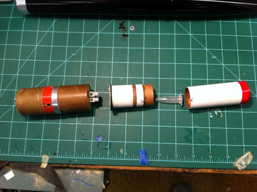
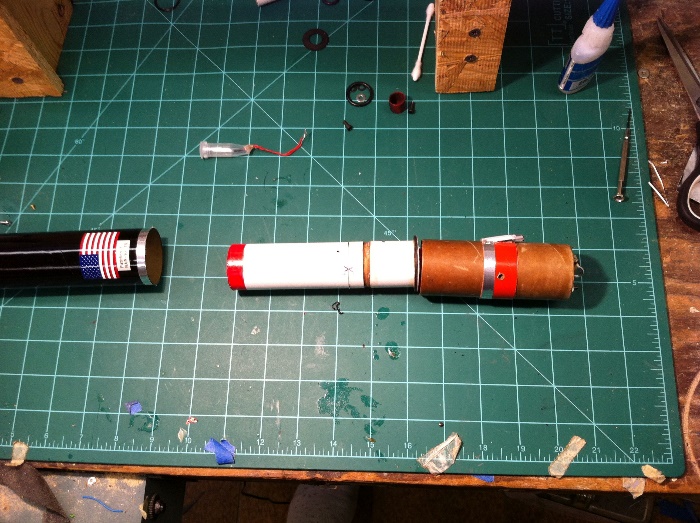
During this pause in Artemis launches, two Artemis Phase II rockets began final development, and construction. The first of the two was named “Pathfinder”, which uses the ideas and techniques I developed for mid power dual deploy. Of a major concern was finding a dual deploy altimeter that can fit inside the BT-60 airframe of these rockets.
Breakdown of the components of the PhaseII MK1 Artemis Booster, Pathfinder — before the paint was applied
This search continued until the last moments before the maiden launch. The brand new (at the time) Perfect Flite Stratologger was chosen as it JUST fit inside the BT-60 electronics bay. Also, the Phase II vehicles were built around a modified version of the “1-B” configuration. A method of electronically controlled ejection charge needed to be developed. After numerous ground tests, the first major test of the charge was used to ground test Garfield and its new configuration to flight test the parachute faring that the phase II rockets would use.
Pathfinder’s AV bay, where the flight computer lives. The orange band would be the only visible portion when installed on the booster.
The Phase II designs were considerably more complex and involved than the phase I rockets. Phase I designs were still primarily hollow model rockets. Phase II was far from that. Internally, the rockets were working machines with very little “hollow” space inside. Before I would feel comfortable launching Pathfinder, I needed a final series of tests on the parachute faring design to make sure the parachute would deploy properly in the Artemis rockets. Garfield was readied for these tests as part of its final missions in service in Phase I launches.
Ground tests went well, and Garfield was readied for the final flights of Phase I missions.

A tight fit for the BT-60 sized AV bay!
June 26, 2011
After nearly a year gap, a modified Garfield rocket was poised to test the proposed anti-zipper design and main parachute faring system. This series of tests will verify the validity of this system for the new generation of Artemis rockets which were designed to test and develop the dual deploy methods needed for high power rockets.
ALS-033 and ALS-034 launched using the “1-E” configuration. Tests were successful, and proved the design was sound.
The parachute fairing was painted with roll patterns for use with video shot of the launch from the ground. The video was used to observe any roll the rocket may have had during its flight.
August 27, 2011
The final two flights of Project Artemis Phase 1 missions were planned in the “1-A” configuration, and the final flight would fly with an on-board video camera. This would be used in conjunction with the previous ground video to document the flight characteristics of the Phase1 Artemis booster design.
ALS-034 flew perfectly, and the zipper-less design behaved as hoped with an entirely different payload section – which places a different set of forces on the fairing than with configuration “1-E”.
ALS-035 flew using the video camera, as well as an on-board altimeter. Due to the weight of the camera system, altitude was only 506 feet.
ALS-034 and 035 flew on E9 motors.
The beginning of Project Artemis – phase II.
Pathfinder set up for ground tests of its deployment charge systems.
In the weeks before the maiden launch of Pathfinder, a series of ground tests were performed to verify and fine-tune much of the hardware on this launch vehicle. A LOT of new design concepts were being tested, including special compartments with seals to hold the ejection charges, “close baffle” systems were also new. Previously, the ejection baffles would be located several inches away from the black powder charge source. Because of space constraints, the baffles in this design had to sit an inch or two from the baffle itself.
Extensive ground tests resulted in a design that seemed to work well. Its true test will be during the first few missions.
Pathfinder booster with the vented side of the main parachute baffle system exposed. (Parachute fairing and nose cone removed).
Pathfinder was designed to use tumble recovery for its apogee event with the main parachute being deployed by the on-board flight computer closer to the ground. All ground tests were completed, and all looked good for the maiden launch of Pathfinder. The on-board electrical system was powered by a 12-volt A-23 alkaline battery. This was chosen both for its small size, and light weight.
Along the side of the rocket was an external electrical conduit for sending the voltage to fire the apogee charge, which was in the lower booster system. In the next Phase II rocket, this lower booster charge would sit behind an ejection baffle. This aspect of the design was carried from experimental launches with the Perseus rocket “Zephyr”.
Because the phase II rockets were not simple hollow rockets, they were considerably heavier, so higher performance composite motors were used. Pathfinder flew using Aerotech F-24 motors for all flights except for the final one, which used the F-35 motor.
October 8, 2011
The maiden launch of Pathfinder (XR2/DD MK I). A lot of work went into this rocket, and the future of the level 1 rocket rode on the success of this launch. Three flights were planned.
ALS-036 pre launch picture.
First up, mission ALS-036. Pathfinder launched from Harmon field far away from the spectators in a “heads up” flight. Meaning, everyone keep your eyes on this in case something goes wrong, and you need to take cover!
ALS-038 Liftoff!
The flight launched gracefully, and the launch was a textbook flight. Everything performed as expected. I was able to let my heart clear my throat after that one!
Pathfinder lifted off to an altitude of 1007 feet, and apogee deployment, and main parachute deployment went perfectly.
The rocket touched down about 100 feet away in the main launch area for my rocket club. With that launch out of the way, the stage was set for two more test flights to push the rocket hardware to observe how robust the designs were.
ALS-037 was again flawless, this time reaching an altitude of 1056 feet, and touching down beautifully. The final flight, ALS-038 reached 908 feet. All flights used the F-24 motor. Pathfinder was then set for deep inspection and preparations for its next flight.
At this point, construction of the next Phase II rocket (XR2/DD MK II) was underway. The next version of the rocket will be carrying more electronics on board, including a video camera. An even stronger motor will be needed, so a 29mm motor system was specified.
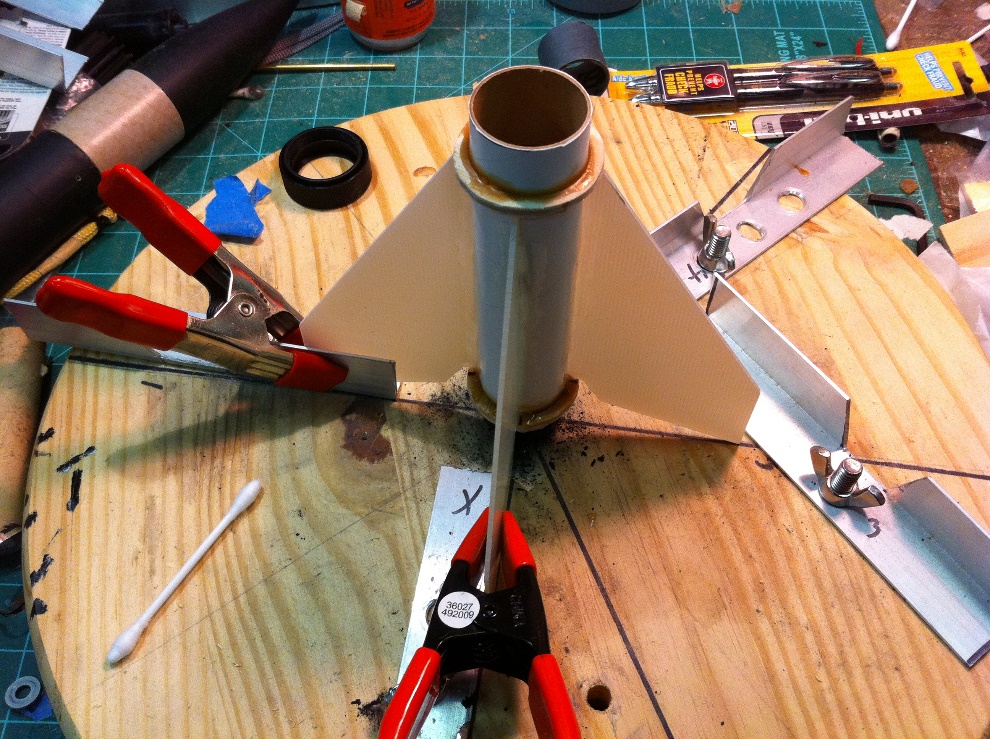
The Artemis Phase II, MK2 booster construction begins with the fin can assembly.
The plastic fin cans that all of the Artemis rockets have used to date was replaced with a custom built system consisting of G-10 fiberglass fins. This was the first time I’ve used them, and the construction of these would teach me how to use fiberglass parts in rocket designs.
The Mark II design would be the first to be fully modular in design allowing for disassembly and repair as needed.
Before this rocket could be fully completed, more test flights were needed from Pathfinder to guide the final form of the Mark II design.
October 22, 2011
Two more launches from Pathfinder testing for consistency in the operation of its various components. The first launch, ALS-039 launched beautifully, but at apogee, the drogue charge lost pressure through a failure of one of the screws that held the side hatch closed. As a result, Pathfinder was on a ballistic return to the ground. The main parachute deployed at the proper height, but while Pathfinder was moving at a high rate of speed. If there was any test of the anti-zippering system, this was it…and the anti-zipper system worked great. No damage to Pathfinder, and after a few string and bailing wire type repairs to the door hatch, was ready for another flight.
ALS-040 was next, and this mission was picture perfect. One more flight was planned for Pathfinder, and this one would push the design hard.
December 26, 2011
After some slight re-design of the door hatch (which forced an “eleventh-hour” design change to the drogue charge door on the Mark II rocket), Pathfinder was ready for its sixth, and final, mission. This time flying on an Aerotech F-35 motor. At this point, it was understood that the Mark II vehicle would fly on an F-40 motor for most its missions, so I wanted to have some similar base line to go by for the new rocket.
Pathfinder lifted off on mission ALS-041 at the highest-powered flight of any of my rockets to date. It was a mildly cold day, not too bad (temperatures in the mid 40’s). Pathfinder reached an altitude of 1,360 feet. An impressive altitude for my rockets, and the highest altitude for any Artemis rocket until then! Signs of trouble were observed when the main parachute did not deploy. Fortunately, the rocket was light enough that no serious damage was observed from the drogue only landing.
Further observation showed that neither of the computer controlled events occurred, though I could see indications of the commands being issued in the flight data. The situation was noted, and I moved forward to the next step with the Mark II design, and its maiden voyage.
Mark II rocket takes shape.
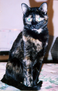
CG’s cat, Nala.
Final construction of the Artemis XR2/DD MKII rocket was underway, and the rocket was rapidly being outfitted for its intense list of objectives to be met by the end of the year to prove and test the technology for use in my Level 1 rocket, XR6 / Nesaru. As the new rocket either clears or proves a portion of the tech, the larger version of said tech would be finalized on Nesaru, inching it one step closer to its’ maiden launch / my level 1 certification attempt.

Nala Rocket’s banner, featuring Nala’s paw print. Nala Rocket was dedicated to his furry friend of 17 years when shortly after he lost her.
The new rocket would be painted black with distinctive red tail fins. A name would be chosen to honor the Tuskegee Airmen, which my Grandfather was an original member. Shortly before the maiden launch, I lost my furry friend of 17 years, Nala. I decided to dedicate this rocket to my pet cat. The “official flag” for the rocket was created.
Phase II MKII fin can / booster section is coming together.
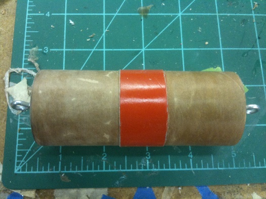
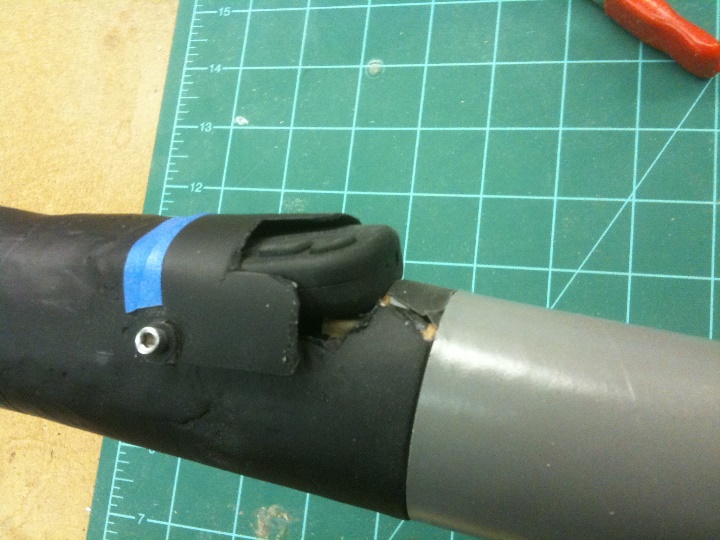
PhaseII Mark II booster’s main parachute deployment system. The Altimeter bay is to the right (orange band in the middle) To the right of it is the deployment charge “top hat” where the charge would go (a modified centrifuge tube) To the right of the centrifuge tube is the “close-in” baffle.
The top view of the deployment system components. (Left) is the vent side of the “close in baffle”, to the right is the “top hat” which holds the centrifuge tube with the deployment charge.,
This image shows the order in which all of the components will fit together. At the far left is the airframe housing where all the components will go. This image shows the components rotated 180 degrees from the first exploded view.
The angle of the components in this picture is flipped 180 degrees from the “exploded view”. Seen to the far right, the electronics bay. To the left of that is the deployment charge top hat seated against the E. Bay, which fits into the baffle. The whole system slides into the airframe section of the rocket where all of these components are housed.
All of the components are now together, and installed inside the airframe section that houses the internal “close-in” baffle system. In these pictures, the external airframe components are from Pathfinder.
The parachute fairing and nose cone are now attached to the completed upper baffle system and electronics bay.
This picture shows the nosecone camera system for Nala1 (Phase II, MKII booster). The camera system has been undergoing flight tests on board the Aurora rockets for several months.
Another view showing the keychain camera, This camera nose cone system also features a small payload compartment for use with possible electronic experiments in the future.
A quick note on the centrifuge tube for ejection charge management.
The idea here is to use these vs. trying to clumsily stow away loose black powder into canisters on the rocket somewhere. This created a self contained tube modified to hold the ignition charge at one end. After almost a year of ground testing, Nala1 would be the rocket to test this item in flight for the first time. This system would be used on all of my dual deploy rockets after the successful testing on-board Nala1.
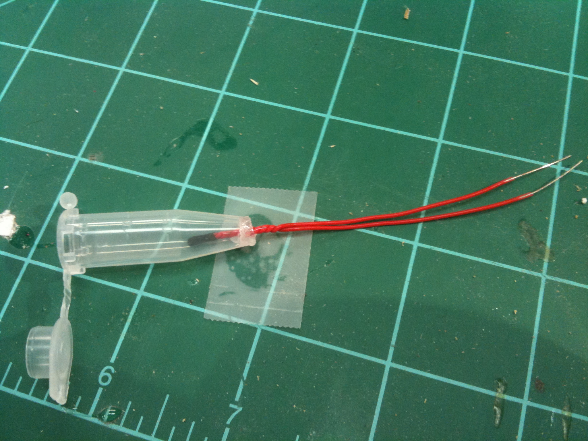
The Centrifuge based ejection charge system.
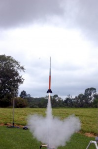
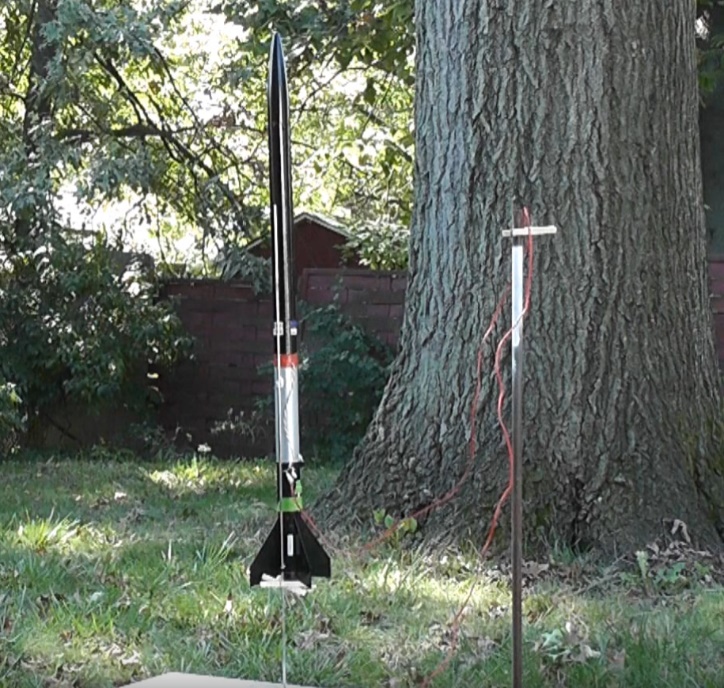
March 25, 2012
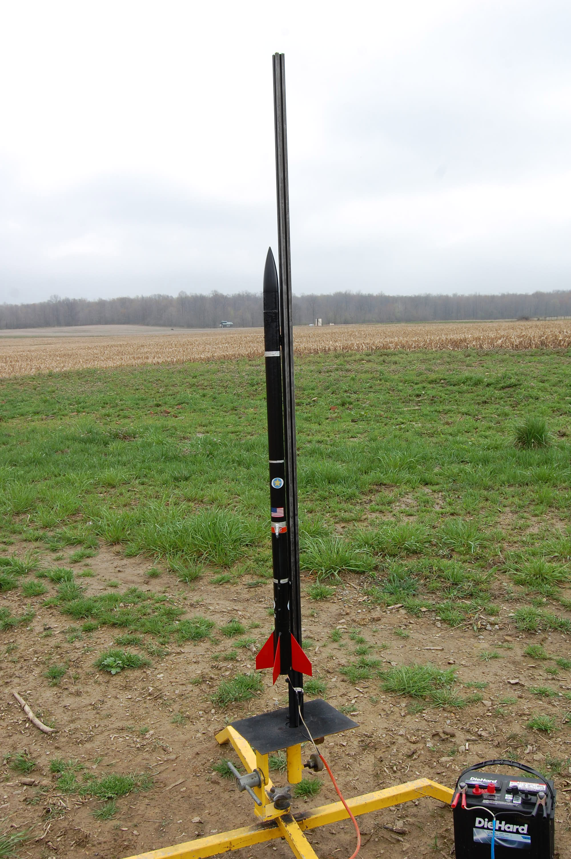
Nala1 on the launch pad.
ALS-042 liftoff!
The date of the maiden voyage of the Artemis XR2/DD – MK II rocket, now named “Nala1”. At liftoff, the weight of the total Nala1 rocket stack weighs in at 1.5 lbs. So, the trusty launch pad that launced so many of my rockets to this point could not be used. Instead, MTMA’s high power launch pad was used to support the rocket at liftoff.
Nala1 lifted off on an overcast day on mission ALS-042, and reached an altitude of 1040 feet using an Aerotech F40 motor. At the time of the liftoff (and unknown to me and the club), low hanging clouds moved in – maybe at the 800 foot level or so, so apogee could not be seen. Only heard. We had to guess that all went fine until Nala1 emerged from below the low cloud bank. Yes! The event had occurred, and Nala 1 was in tumble recovery mode. At 400 feet, the main parachute was deployed to bring Nala1 gently to the ground. The first flight of my most sophisticated rocket to that point was a total success!
Maiden voyage of Nala1
There was also an on-board video camera for this mission, though no video was captured as it malfunctioned shortly before launch. Only ground still shots and the data are available to document this first mission.
On later missions (as you will see), this on-board camera would deliver some of the most amazing and iconic rocketry pictures in my collection of rocket launch pictures.
“Nala Rocket” – as it became known – was returned to my workshop for disassembly and inspection before its next launch.
Of note here, Nala1 was the first fully modular rocket design – most of the rocket could be dis-assembled for repair and inspection, and re-assembled. This is no easy feat, and was a somewhat problematic design aspect that required creative solutions to overcome, but all essential to the Nesaru design. For Nesaru, this modularity aspect was an essential part of its design.
April 29, 2012
Nala1 launches on mission ALS-043, reaching an altitude of 1056 feet on a calm wind day – also using the F40 motor. Launch was nominal, and this time the camera works!
ALS-043 liftoff
This textbook launch returned one of the many “iconic views” from apogee that Nala1 became known for.
Post inspection of all the systems revealed damage to the apogee baffle system was found. This damage was due to the plastic cap on the motor’s ejection charge well shooting forward, destroying the baffle.
Such events were expected as these baffles “sit” much closer to the black powder charge than any that I have been aware of.
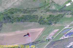
ALS-043 post apogee view with the booster section trailing behind on the recovery harness…
Dealing with (and solving) this situation was critical to the successful operation for Nesaru. Another design idea on the books went into construction.
June 9, 2012
This launch date was set for an ambitious mission. The goal on this one was to see what the “turn around” time for Nala1 ultimately is. Two successive days of launched was planned. One launch on the first day (ALS-044) and two the following day.
ALS-044 had a successful flight to apogee, reaching 960 feet on the F40 motor. The new baffle performed as it should, but the increased back-pressure created by the new design created by the charges going off caused separation of the booster. No major damage that couldn’t be dealt with.
June 10, 2012
After a slight modification, NALA1 was readied for its next flight of the day, ALS-045, also on the F-40 motor. That flight went well; main parachute was late “unfolding” Minor damage noted as Nala1 landed on the drogue parachute only. Maximum altitude achieved: 982 feet.
ALS-046 was about two hours later, reaching an altitude of 996 feet. This launch suffered a separation of the main baffle system. A combination of variations in the strength of the black powder charge, as well as “shock” from the charge going off played a role here. The “shock wave” from the charge going off was cracking the epoxy bond that held the charge canister and baffle system. A re-design of the baffle systems to handle both conditions was needed, as this method will be used on ALL rockets of any kind moving forward for electronic parachute deployment.
The conditions causing the baffle failures were understood, and I felt confident that a robust system I designed on the books just in case would solve the issues.
July 14, 2012
Nala1 was poised for liftoff on mission ALS-047 to test out all the re-designed baffles as well as changes to how some of the modular components of Nala1 are connected. Nala1 reached an altitude of 1063 feet using the F40 motor, and all events occurred as they should, and no component failures of any kind. Nala1 landed in a tree, and had to be recovered using a long pole.
July 28, 2012
After reviewing flight data from Nala1’s flights to date, I determined that the drogue parachute was not necessary, and it caused more issues than it solved. So the rocket was slated for “tumble” recovery. This date was the second back-to-back launches on the same day to test dome of the design refinements designed to speed up return to flight times.
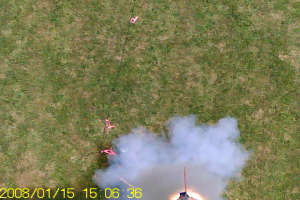
ALS-049 launch as seen from Nala1
ALS-048 was another textbook flight with no issues to report. Nala1 reached an altitude of 1045 feet on an F40 motor. ALS-049 was also trouble free with exception to human error. I mistakenly loaded a charge designed for use in the older baffle system, so there was not quite enough black powder to fully deploy the main parachute with enough force. The new baffle system required a larger volume of black powder for successful parachute deployment.
The Apogee Event. (ALS-049)
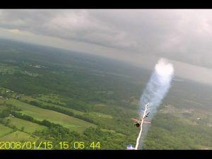
ALS-049 was a launch that occurred during a light drizzle. The video returned from that launch showed an impressive “rainbow” that could only be seen from the rocket @ 1020 feet up looking back to towards the ground! This along with an impressive view looking back towards the launch pad at liftoff. ALS-049 reached an altitude of 1053 feet.
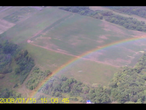
The beautiful rainbow as seen from 1,000 feet. (ALS-049)
October 13, 2012
The last “Phase II” development launch of the Artemis rocket system before the maiden voyage of the Level 1 rocket, Nesaru. This flight had no specific goal other than to log another flight to insure the new baffle systems and securing points for the various modules of Nala1 would all hold together without issue. They did, and ALS-050 was declared a total success, as was the Phase II Artemis project, and all the objectives were met inside the one year window set aside for this project, keeping the Level1 rocket launch date on schedule!
The 50th launch of the Artemis Launch System was a high point for the project as it met all its goals, and all on time. ALS-050 logged an altitude of 1094 feet – all events occurred in textbook fashion.
The next few flights for Nala1 were set as bonus, fun missions. The Artemis rockets were always intended to reach an altitude of 2,000 feet, yet the launches were all under 1,100 feet to date. NALA1 was prepared to be the first Artemis rocket to meet that goal, and the date was set for the February 2013.
February 9, 2013
While Nesaru was undergoing a few “teething pains” with its first two launches over the winter, Nala1 was set for its high altitude attempt.
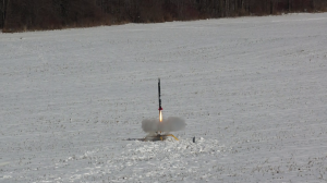
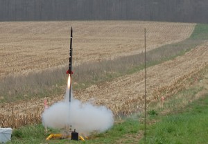
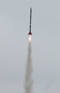
Nala1 lifting off on mission ALS-051
ALS-051 lifted off on a snow covered launch day on an Aerotech G-64 motor. She screamed from the pad, and the noise form the motor filled the field! Nala1 soared to an altitude of 2,052 feet, absolutely
meeting the maximum operating altitude intended for the rocket (any higher, and it would have been difficult to see it – which increases the chances of never getting It back!).
All systems operated flawlessly, and Nala1 returned with a new altitude record for me – which would stand for some time to come.
ALS-051 — soaring to 2052 feet.
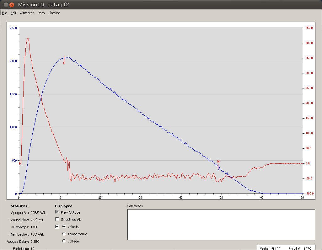
Flight data from ALS-051
April 27, 2013
Nesaru was prepped for the first of what would be her final flights before retirement. Again, no specific point to the remaining missions other than to enjoy the launches. A new generation of mid power dual deploy rockets would take over routine launches of this type in smaller fields with less complicated launch procedures.
ALS-052 was a pretty routine launch, reaching an altitude of 966 feet on an F40 motor.
ALS-053, the final launch of Nala1 was an oddball flight. At liftoff, theF40 motor was chuffing in an extreme way, at one point, when the rocket was maybe 100 feet in the air, the motor stopped all together, then came up to pressure for good from that point. But not before Nala1 started to arc over. When the motor came to pressure, Nala1 was at a 45 degree angle, heading over a heavily wooded area. Because apogee happened with Nala1 flying horizontal at a high rate of speed, the parachute deployment event caused the rocket to separate into two parts. The booster section was recovered in a back yard of a house, while the upper section landed in dense, dense wooded abandoned lot. It took a over an hour of several of us combing the area to find the rocket. The total size of the area is slightly larger than your typical property size, but with a small stream running through it. That tells you how crazy thick the bushes were in there!
With Nala1 safely recovered, the Artemis program came to a close on a oddball, but good note.
In Conclusion
The Artemis medium booster project was a challenging and sometimes grueling one, but ultimately, it was a lot of fun! As crazy as this project was, it was only 1/3 of the total activity with parallel projects happening with:
Project Perseus – The testing and proving of my first design aided by, and optimized with rocket CAD software. It would ultimately be chosen as the basis for the level 1 rocket, the XR6.
Project Aurora – The project aimed at perfecting the camera technology that was later used on Nala1 Rocket, and every rocket of mine ever since. Another goal of Project Aurora was to learn and get the feel for composite rocket motors that would have to be used for Pathfinder, Nala1, and every high-power rocket. I need to develop my composite motor techniques for reliable composite motor launches, which did happen, thanks to this project.
So much of what was learned with Project Artemis has resonated strongly with every single rocket launch of mine ever since.